VHDL: Pong
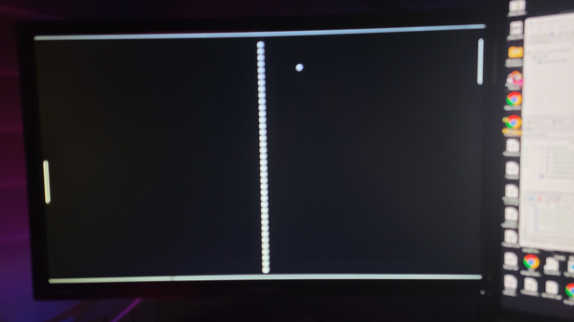
In order to further my knowledge of FPGA logic and VHDL I created a simple Pong game.
While simple in theory, this project required three clocked processes, a VGA signal generator and some interesting logic.
Update 2023-11-14: I’d like to note that some aspects of this project do not contain an optimized logic implementation. When I wrote this code, I was very new to not only VHDL but also FPGA logic as a whole. After taking ELEC 271: Introduction to Digital Systems, I have learned the reasons behind why this project took so long for Quartus to synthesize.
VGA Controller
The first step in creating Pong in VHDL was to create a VGA controller. VGA is a very simple interface for displaying images on a display. It works on the basis of horizontal and vertical clock pulses to indicate what pixel the analog color values are currently representing. I started this project by writing a simple VGA controller that made the entire screen purple. Why purple? Because I like purple, and because I wanted to make sure that the DAC (Digital to Analog Converter) was operating correctly. By displaying a color other than black or white, I was able to test its functionality.
I chose to generate a 640 x 480 image. This is one of the lower standards of VGA and having less pixels, requires a lower clock speed. The DE2 only has a 50 MHz clock, and this image standard requires a 25 Mhz clock. Therefore I only have to half the DE2’s clock speed. This is also much easier than using a PLL (Phase Locked Loop), further simplifying this project.
In order to half the clock speed, I simply used the following process statement to assign CLOCK_25, my 25MHz clock to not itself every time the 50MHz clock had a rising edge.
1
2
3
4
5
6
process(CLOCK_50) is
begin
	if rising_edge(CLOCK_50) then
		CLOCK_25 <= not CLOCK_25;
	end if;
end process;
Now that I have the clock signal generated, I used it to generate the horizontal and vertical pixel clocks. To to this, I simply counted out the horizontal pixels on every clock tick, when the horizontal pixel counter reached the end, I reset it and added one to the vertical counter. If the vertical counter is full, it will also reset, triggering the end of displaying one frame.
1
2
3
4
5
6
7
8
9
10
11
12
13
process(CLOCK_25) is
begin
	if rising_edge(CLOCK_25) then
		if x < 799 then
			x <= x + 1;
		else
			x <= 0;
			if y < 524 then
				y <= y + 1;
			else
				y <= 0;
			end if;
		end if;
Since the values of the horizontal and vertical signal lines are based on the pixel counters, I added the following if statements to assign values to the horizontal and vertical clock (sync) signals based on the counter values.
1
2
3
4
5
6
7
8
9
10
if x < (640 + 16) or x >= (640 + 16 + 96) then
	VGA_HS            <= '1';
else
	VGA_HS            <= '0';
end if;
if y < (480 + 10) or y >= (480 + 10 + 2) then
	VGA_VS            <= '1';
else
	VGA_VS            <= '0';
end if;
Finally, I generated the color signals. Note that the above counters go outside of the valid image ranges. This is to generate the sync pulses. Sync pulses are used to let the monitor know when the end of the horizontal line, and when the end of the frame occur. In older TVs, this was used to reset the laser to the top left, like a typewriter. When the counters are within valid range, the color signals need to display the colors of the pixels as they are displayed. When the counters are outside the valid image range, and a sync pulse is occurring, the color lines need to be blank. In order to implement this functionality, I implemented a rangeValid signal.
1
2
3
4
5
if x < 640 and y < 480 then
	rangeValid        <= '1';
else
	rangeValid        <= '0';
end if;
Finally I wrote some code to display a color on the screen when the range is valid, and display black when it isn’t.
1
2
3
4
5
6
7
8
9
10
11
if rangeValid = '1' then
	-- set dac to purple
	VGA_R <= (others => '0');
	VGA_G <= (others => '1');
	VGA_B <= (others => '1');
else
	-- turn off color output
	VGA_R <= (others => '0');
	VGA_G <= (others => '0');
	VGA_B <= (others => '0');
end if;
I should also note that I had to add the following lines of code in order to make the VGA DAC included with the DE2 to work correctly.
1
2
3
4
-- use sysclock for vga clk (reduses color bugs)
VGA_CLK      <= CLOCK_50;
VGA_SYNC     <= '1';
VGA_BLANK    <= VGA_HS and VGA_VS;
Pong Code
I won’t go into detail about how I wrote the game code because it is almost entirely if statement based logic based off of the current horizontal and vertical cursor position.
Entity Declaration
The VHDL top entity contains the VGA clock, color and sync signals. It also contains all of the DE2’s 7 segment displays. I used two of the displays to display the score, and set the rest to turn off. I also included some keys and LEDs for debugging.
1
2
3
4
5
6
7
8
9
10
11
12
13
14
15
16
17
18
19
20
21
22
23
24
25
26
27
28
29
30
31
32
33
34
35
36
37
library ieee;
use ieee.std_logic_1164.all;
use ieee.numeric_std.all;


entity top is
    port(
        -- VGA Output
        VGA_R        : out std_logic_vector(9 downto 0);
        VGA_G        : out std_logic_vector(9 downto 0);
        VGA_B        : out std_logic_vector(9 downto 0);
        VGA_CLK      : out std_logic;
        VGA_BLANK    : out std_logic;
        VGA_HS       : inout std_logic;
        VGA_VS       : inout std_logic;
        VGA_SYNC     : out std_logic;

        HEX0         : out std_logic_vector(6 downto 0);
        HEX1         : out std_logic_vector(6 downto 0);
        HEX2         : out std_logic_vector(6 downto 0);
        HEX3         : out std_logic_vector(6 downto 0);
        HEX4         : out std_logic_vector(6 downto 0);
        HEX5         : out std_logic_vector(6 downto 0);
        HEX6         : out std_logic_vector(6 downto 0);
        HEX7         : out std_logic_vector(6 downto 0);


        -- Clock Input (50 MHz)
		CLOCK_50     : in  std_logic;

        LEDG0        : out std_logic;
        LEDG1        : out std_logic;
        KEY0         : in  std_logic;
        KEY1, KEY2   : in  std_logic

    );
end entity;
The Architecture
The Architecture consists of four main sections: The 7 segment controllers, the VGA logic discussed above, the game logic, and two simple “AIs” that play against each other. I say “AI” in quotes because they are really just a few lines that move the paddles close to the
The 7 segment displays operate through a controller I made in another project. As previously mentioned, the unused displays are disabled.
1
2
3
4
5
6
7
8
9
10
11
12
13
14
15
16
17
18
rightScore : work.sevensegments(behavioral)
	port map(
		i_dispNum => scoreRight,
		o_DispSeg1 => HEX4,
		o_DispSeg2 => HEX5
	);

leftScore : work.sevensegments(behavioral)
	port map(
		i_dispNum => scoreLeft,
		o_DispSeg1 => HEX6,
		o_DispSeg2 => HEX7
	);

HEX0 <= (others => '1');
HEX1 <= (others => '1');
HEX2 <= (others => '1');
HEX3 <= (others => '1');
The rest of the code is available on my Haswell GitHub Repository.