STM32 FreeRTOS CAN Bus
Introduction
Continuing from where I left off with the UART drivers, the next logical step was to apply what I had learned to a more complicated interface. Controller Area Network, or CAN bus, is a protocol used on automobiles for its extreme resiliency and resistance to electrical interference. For these reasons, it is the main communication system used aboard the Queen’s Formula SAE car.
CAN Bus
Before I start, it is necessary to briefly introduce the CAN bus protocol. CAN bus is a multi-master, multi-drop, differential signaling bus that was first developed in 1986 by Bosch. It operates on a priority based system where lower ID numbers are given higher message priority. The bus employs various EMI rejection and fault tolerance mechanisms, but for the purpose of this article it is only necessary to know the base structure of a message.
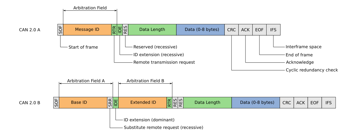
A CAN bus message can either contain a standard ID, consisting of 11 bits, or an extended ID, consisting of 31 bits. Following the ID is a four bit number ranging from zero to eight, and signifying the length of the data in the bytes. Finally, each CAN bus frame can contain up to eight bytes of data for a total of 64 bits or one full word.
Hardware Abstraction
Since I am writing yet another driver for my FreeRTOS system, the first step is to break apart the hardware from the software. For CAN bus, this was done through the use of a Hardware Abstraction Layer (HAL). The HAL consists of having five main functions: Initialization, data transmission, data reception, and two wrapper functions to request if the peripheral is ready to read from or transmit.
Initialization
To initialize the CAN peripheral on the STM32, it must first be enabled by the reset and clock control register (RCC). Secondly, the GPIO pins being used must be enabled and the multiplexer must be set to attach the pins to the CAN controller. Much of the CAN bus initialization is similar to the UART initialization described in another article, thus I have attached the code and will only discuss some of the challenges I faced.
1
2
3
4
5
6
7
8
9
10
11
12
13
14
15
16
17
18
19
20
21
22
23
24
25
26
27
28
29
30
31
32
33
34
35
36
37
38
39
40
41
42
43
44
45
46
47
48
49
50
51
52
53
54
55
56
57
58
59
60
61
62
63
/**
 * @brief Initialize a CAN bus
 *
 * @param CAN The CAN bus to initialize
 * @param bitrate CAN Bitrate (50, 100, 125, 250, 500, 1000 kbps)
 * @param NART TRUE to disable automatic retransmission. Should be FALSE for normal operation
 * @param pin_tx GPIO PIN (automatic setup for can bus)
 * @param pin_rx GPIO PIN (automatic setup for can bus)
 * @returns HAL_CAN_OK or HAL_CAN_xx_ERR upon failure
 */
static inline uint8_t hal_can_init(CAN_TypeDef * CAN, CAN_BITRATE bitrate, bool NART, uint16_t pin_tx, uint16_t pin_rx){
    // Enable the CAN bus clock
    if(CAN == CAN1) RCC->APB1ENR |= RCC_APB1ENR_CAN1EN;
    if(CAN == CAN2) RCC->APB1ENR |= RCC_APB1ENR_CAN2EN;
    // Set up the GPIO pins
    gpio_set_mode(pin_tx, GPIO_MODE_AF);
    gpio_set_af(pin_tx, 9); // GPIO Alternate function 9 -> CAN Bus
    gpio_set_mode(pin_rx, GPIO_MODE_AF);
    gpio_set_af(pin_rx, 9);

    // Request the CAN bus to enter into initization mode
    SET_BIT(CAN->MCR, CAN_MCR_INRQ);
    while(!(CAN->MSR & CAN_MSR_INAK));

    // Reset All other bits leaving INRQ
    CAN->MCR = 0x1UL; // NOTE: This assignment is meant to clear the register. Use of (=) operand is not a mistake

    // Enable automatic bus error management
    SET_BIT(CAN->MCR, CAN_MCR_ABOM);
    // Configure Automatic Retransmission
    if(NART) SET_BIT(CAN->MCR, CAN_MCR_NART);
    // Disable Time Controlled Communication Mode (extension of CAN protocol)
    CLEAR_BIT(CAN->MCR, CAN_MCR_TTCM);
    // Enable FIFO mode for tx registers
    SET_BIT(CAN->MCR, CAN_MCR_TXFP);
    // Setup bus bitrates
    CAN->BTR &= ~((0x03UL << 24) | (0x07UL << 20) | (0x0FUL << 16) | (0x1FFUL)); // Zero out the register
    CAN->BTR |=  (uint32_t)((((can_configs[bitrate].TS2-1) & 0x07) << 20) | (((can_configs[bitrate].TS1-1) & 0x0F) << 16) | ((can_configs[bitrate].BRP-1) & 0x1FF)); // Set up the bit timing
                                                                                                                               // Initialize the filter registers
    SET_BIT(CAN1->FMR, CAN_FMR_FINIT);           // Enter into initialization mode
    CLEAR_BIT(CAN1->FMR, CAN_FMR_CAN2SB);        // Clear the Filter Selection register
    CAN1->FMR |= (0xEUL << CAN_FMR_CAN2SB_Pos); // Set filters (0-13 -> CAN1) & (14-28 -> CAN2)
    uint8_t f1_status = hal_can_setFilter(0, 1, 0, 0, 0x0UL, 0x0UL);
    uint8_t f2_status = hal_can_setFilter(14, 1, 0, 0, 0x0UL, 0x0UL);
    CLEAR_BIT(CAN1->FMR, CAN_FMR_FINIT);              // Deactivate initialization mode

    if(f1_status != HAL_CAN_OK) return f1_status;
    if(f2_status != HAL_CAN_OK) return f2_status;

    // Enable the bus
    // Request to leave initialization mode
    CAN->MCR &= ~(CAN_MCR_INRQ);
    uint32_t timeout = 9999;
    for(uint32_t wait_ack = 0; wait_ack < timeout; wait_ack++){
        if((CAN->MSR & CAN_MSR_INAK) == 0){
            // Return: Success if CAN enables sucessfully
            return HAL_CAN_OK;
        }
        for(uint32_t spin = 0; spin < timeout; spin++);
    }
    // Return error if CAN not initialized by end of timeout
    return HAL_CAN_INIT_ERR;
}
While most of the initialization code is identical to that of the code used for the UART driver, the CANbx peripheral on the STM32 requires that the message “filter” be set up in order to receive any messages. At first I did not realize that this was mandatory, as it is not mentioned anywhere within the datasheet or the STM32Cube autogenerated code. Luckily, I happened to find this repository from the UBC Solar Team, which helped me to configure the filters to not block any\of the messages.
Message Reception
Similarly to the Initialization code, receiving a message over CAN bus is nearly identical to UART. However, one key difference to note between the two is that the CAN peripheral contains multiple reception registers called mailboxes. The CAN interface also requires that a mailbox be “freed”, or returned to the hardware after the data has been read from it.
1
2
3
4
5
6
7
8
9
10
11
12
13
14
15
16
17
18
19
20
21
22
23
24
25
26
27
28
29
static inline void hal_can_read(CAN_TypeDef * CAN, can_msg_t * rx_msg){
    // Determine Message ID format (Identifier Extension)
    rx_msg->format = (CAN_RI0R_IDE & CAN->sFIFOMailBox[0].RIR);
    if(rx_msg->format == STANDARD_FORMAT){
        rx_msg->id = (CAN_RI0R_STID & CAN->sFIFOMailBox[0].RIR) >> CAN_TI0R_STID_Pos;
    }
    else{
        rx_msg->id = ((CAN_RI0R_EXID | CAN_RI0R_STID) & CAN->sFIFOMailBox[0].RIR) >> CAN_RI0R_EXID_Pos;
    }

    // Data Frame = 0 | Remote Frame = 1
    rx_msg->type = (CAN_RI0R_RTR & CAN->sFIFOMailBox[0].RIR);

    // Message data length
    rx_msg->len = (CAN_RDT0R_DLC & CAN->sFIFOMailBox[0].RDTR) >> CAN_RDT0R_DLC_Pos;

    // Unload the data
    rx_msg->data[0] = (uint8_t)((CAN_RDL0R_DATA0 & CAN->sFIFOMailBox[0].RDLR) >> CAN_RDL0R_DATA0_Pos);
    rx_msg->data[1] = (uint8_t)((CAN_RDL0R_DATA1 & CAN->sFIFOMailBox[0].RDLR) >> CAN_RDL0R_DATA1_Pos);
    rx_msg->data[2] = (uint8_t)((CAN_RDL0R_DATA2 & CAN->sFIFOMailBox[0].RDLR) >> CAN_RDL0R_DATA2_Pos);
    rx_msg->data[3] = (uint8_t)((CAN_RDL0R_DATA3 & CAN->sFIFOMailBox[0].RDLR) >> CAN_RDL0R_DATA3_Pos);
    rx_msg->data[4] = (uint8_t)((CAN_RDH0R_DATA4 & CAN->sFIFOMailBox[0].RDHR) >> CAN_RDH0R_DATA4_Pos);
    rx_msg->data[5] = (uint8_t)((CAN_RDH0R_DATA5 & CAN->sFIFOMailBox[0].RDHR) >> CAN_RDH0R_DATA5_Pos);
    rx_msg->data[6] = (uint8_t)((CAN_RDH0R_DATA6 & CAN->sFIFOMailBox[0].RDHR) >> CAN_RDH0R_DATA6_Pos);
    rx_msg->data[7] = (uint8_t)((CAN_RDH0R_DATA7 & CAN->sFIFOMailBox[0].RDHR) >> CAN_RDH0R_DATA7_Pos);

    // Release the mailbox to hardware control
    SET_BIT(CAN->RF0R, CAN_RF0R_RFOM0);
}
One important note to make is that this code only reads from the first of the three mailboxes. This is because I plan to trigger an interrupt on message reception, thus the other two mailboxes should never be in use.
The HAL also contains a wrapper function to check if the mailbox is full. This function will not be used within the FreeRTOS code, but exists incase a future user wishes to switch to a polling system for message reception.
1
2
3
4
5
6
7
8
9
10
11
12
/**
 * @brief Get if a CAN message is pending in the CAN bus FIFO
 *
 * @param CAN The CAN bus FIFO to check
 * @returns TRUE if a message is pending
 * @returns FALSE if the FIFO is empty
 */
static inline bool hal_can_read_ready(CAN_TypeDef * CAN)
{
    // Check for pending FIFO 0 messages
    return CAN->RF0R & 0x3UL;
}
Message Transmission
The STM32 CAN interface features three transmission mailboxes that can be configured to either work based on a priority system, or as a hardware managed FIFO. When writing this code, I chose to go with the latter, allowing me to ensure that once a message is deposited in a mailbox, it will be sent in a relatively quickly manner. This avoids the possibility of a lower priority message not making it onto the bus due to higher priority messages being sent first. When operating in the FIFO mode, a message can be deposited into any of the three mailboxes, and will be timestamped and sent out in order by the hardware. To send a message, the user must select the bus and the transmission mailbox to use. Similarly to the UART transmission code, the mailbox is first checked to ensure it is empty, and then is loaded with the message data. One difference between UART and CAN is that the CAN mailbox must be released to hardware with the Transmit Request bit before the message can be sent.
1
2
3
4
5
6
7
8
9
10
11
12
13
14
15
16
17
18
19
20
21
22
23
24
25
26
27
28
29
30
31
32
33
34
35
36
37
38
39
40
41
42
43
/**
 * @brief Send a CAN message. Must wait for message to send before attempting another transmission
 *
 * @param CAN the CAN bus to send on
 * @param tx_msg pointer to the message to send
 * @param mailbox The TX mailbox to use (0..2). Use 0 as default
 * @return uint8_t HAL_CAN_OK or HAL_CAN_xx_ERR on on error
 */
static inline uint8_t hal_can_send(CAN_TypeDef * CAN, can_msg_t * tx_msg, uint8_t mailbox) {
    // Check the mailbox is empty before attempting to send
    if(CAN->sTxMailBox[mailbox].TIR & CAN_TI0R_TXRQ_Msk) return HAL_CAN_MAILBOX_NONEMPTY;
    if(mailbox > 2) return HAL_CAN_MAILBOX_SELRNG_ERR;

    // Create temp variable to store mailbox info
    uint32_t sTxMailBox_TIR = 0;
    if(tx_msg->format == EXTENDED_FORMAT){
        // Extended msg frame format
        sTxMailBox_TIR = (tx_msg->id << CAN_TI0R_EXID_Pos) | CAN_TI0R_IDE;
    }
    else{
        // Standard msg frame format
        sTxMailBox_TIR = (tx_msg->id << CAN_TI0R_STID_Pos);
    }

    // Remote frame
    if(tx_msg->type == REMOTE_FRAME){
        SET_BIT(sTxMailBox_TIR, CAN_TI0R_RTR);
    }

    // Clear and set the message length
    CLEAR_BIT(CAN->sTxMailBox[mailbox].TDTR, CAN_TDT0R_DLC);
    SET_BIT(CAN->sTxMailBox[mailbox].TDTR, (tx_msg->len & CAN_TDT0R_DLC));

    // Load the DR's
    CAN->sTxMailBox[mailbox].TDLR = (((uint32_t) tx_msg->data[3] << CAN_TDL0R_DATA3_Pos) | ((uint32_t) tx_msg->data[2] << CAN_TDL0R_DATA2_Pos) | ((uint32_t) tx_msg->data[1] << CAN_TDL0R_DATA1_Pos) | ((uint32_t) tx_msg->data[0] << CAN_TDL0R_DATA0_Pos));
    CAN->sTxMailBox[mailbox].TDHR = (((uint32_t) tx_msg->data[7] << CAN_TDH0R_DATA7_Pos) | ((uint32_t) tx_msg->data[6] << CAN_TDH0R_DATA6_Pos) | ((uint32_t) tx_msg->data[5] << CAN_TDH0R_DATA5_Pos) | ((uint32_t) tx_msg->data[4] << CAN_TDH0R_DATA4_Pos));

    CAN->sTxMailBox[mailbox].TIR = (uint32_t)(sTxMailBox_TIR | CAN_TI0R_TXRQ);

    // Return read OK
    return HAL_CAN_OK;

}
Again, a wrapper function is provided to see if the mailbox is empty. This function can be polled to check if the message is pending or has been sent.
1
2
3
4
5
6
7
8
9
10
11
/**
 * @brief Get is the Transmit Mailbox is empty
 * @param CAN The CAN bus mailbox to check
 * @param mailbox The TX mailbox to use (0..2). Use 0 as default
 * @return true if the mailbox is empty
 * @return false if the mailbox is pending
 */
static inline bool hal_can_send_ready(CAN_TypeDef * CAN, uint8_t mailbox){
    // Check to see if mailbox is empty
    return !(CAN->sTxMailBox[mailbox].TIR & CAN_TI0R_TXRQ_Msk);
}
FreeRTOS Interface
Exactly like the UART interface, the FreeRTOS interface contains all of the task safe calls to the HAL. The interface also provides the interrupt based message reception code. Most of the code written for the CAN bus was taken from the UART interface with a few key exceptions. First of all, the CAN interface uses a counting semaphore in addition to three binary semaphores for managing the transmit mailboxes. Secondly, the task responsible for managing the message reception loads the messages into a hash table such that they can be accessed by other tasks. This methodology may be changed in the future but it serves fine for now.
Message Reception
Message reception consists of an interrupt paired with a FreeRTOS task. The interrupt is triggered upon message reception and is designed to move messages from the hardware FIFO into the FreeRTOS stream buffer.
1
2
3
4
5
6
7
8
9
10
11
12
13
14
15
16
17
18
19
20
21
void CAN1_RX0_IRQHandler(void){
    // Initialize a variable to trigger context switch to false
    BaseType_t xHigherPriorityTaskWoken = pdFALSE;
    // Temp message to store the incoming data
    can_msg_t rx_msg;

    // Utilize the hal to read the data and release the FIFO
    hal_can_read(CAN1, &rx_msg);

    // Send the recieved data into the stream buffer
    xStreamBufferSendFromISR(
            CAN1_RX.streamHandle,     // Streambuffer to send to
            &rx_msg,                  // Data to copy into the buffer
            sizeof(can_msg_t),        // Size of data
            &xHigherPriorityTaskWoken // Checks if any tasks are waiting on buffer
    );

    // Check and trigger a context switch if needed
    portYIELD_FROM_ISR(xHigherPriorityTaskWoken);

}
Once a message is loaded into the FreeRTOS stream buffer, it is sorted into a hash table by the receive task. This interrupt/task combination was chosen after having a discussion with Thomas Dean, one of the professors at Queen’s University. Initially, I was planning to use either a task or an interrupt for storing the messages. However only using a task came at the disadvantage of possibly missing messages, while only using an interrupt came at the cost of having a lengthy interrupt, which could have caused other problems with the code. Another choice that was made after my discussion with Thomas Dean was to not block the task on the stream buffer like I did with the UART receiver. As pointed out by Thomas Dean, blocking the task on the stream buffer could result in more resources being used by the scheduler to check if the task needs to run or not. It could also result in a longer period of time being required to wake the task. Therefore the task runs on a preemptive schedule where it is guaranteed to run every 10 milliseconds. One other benefit to having the task is the ability to timestamp messages. In future iterations of this code, another possibility would be to cycle through the received messages and display some type of error if stale (old) data is detected.
1
2
3
4
5
6
7
8
9
10
11
12
13
14
15
16
17
18
19
20
21
22
23
24
25
26
27
28
29
30
// LOOP waiting for CAN messages
for(;;){
    // LOOP pulling and sorting messages from the streambuffer
    while(xStreamBufferBytesAvailable(CAN1_RX.streamHandle) > 0){
        // Temp message to store the data comming out of the buffer
        can_msg_t msg;
        // Recieve a message from the buffer
        xStreamBufferReceive(
                CAN1_RX.streamHandle, // Stream Buffer Handle
                (void*)&msg,          // Pointer to RX Buffer (void*)
                sizeof(can_msg_t),    // Size of RX Buffer (Shoudl be size of CAN message)
                10                    // Ticks to Wait
        );
        printf("%ld\n", msg.id);
        // Load the message from the streambuffer into the hash table
        CAN1_DATA[can1_hash(msg.id)] = msg;
        // Timestamp the message
        CAN1_DATA[can1_hash(msg.id)].timestamp = xTaskGetTickCount();
        // printf("%d\n", CAN1_DATA[can1_hash(msg.id)].id);
    }
    // while(xStreamBufferBytesAvailable(CAN2_RX.streamHandle) > 0){
    //     // Temp message to store the data comming out of the buffer
    //     can_msg_t msg;
    //     // Recieve a message from the buffer
    //     xStreamBufferReceive(CAN2_RX.streamHandle, (void*)&msg, sizeof(can_msg_t), 10);
    //     CAN2_DATA[can2_hash(msg.id)] = msg;
    //     CAN2_DATA[can2_hash(msg.id)].timestamp = xTaskGetTickCount();
    // }
    vTaskDelay(100);
}
Please note that I have only posted the receive loop above. For the full code including the task setup, please see the the appropriate page on GitHub.
Message Transmission
When using an interface like UART, message transmission is rather simple. First you must check to see if the peripheral is ready, then deposit the data into the register, and finally wait for the acknowledgement flag from the hardware to ensure the message was sent. When implementing this system with semaphores, a simple binary semaphore can be used to ensure that only one task can access the transmission register at any given time. When working with CAN bus, there are three possible transmission registers to choose from. This rather complicates matters…
To solve this problem, I used two methods. First, I employed a counting semaphore to keep track of the number of mailboxes in use. This provides the blocking mechanism for tasks to wait on a mailbox being available. If the counting semaphore has room in it, then it is known that at least one of the three mailboxes is empty.
1
2
3
4
5
6
// Initialize Semaphores for Transmit Mailboxes
CAN1_TX_Semaphore[CAN_TX_SEMAPHORE_COUNT]  = xSemaphoreCreateCountingStatic(
            2, // Number of TX Mailboxes
            0, // Starting Count (Goes up to Max Count)
            &CAN1_TX_SemaphoreBuffer[CAN_TX_SEMAPHORE_COUNT] // Pointer to static Buffer
    );
Secondly, I used an array of binary semaphores that are indexed to each of the mailboxes. These act identically to the binary semaphores used in the UART implementation. They are stored in an array so that they can be looped through, but more on that later.
1
2
3
4
5
6
7
8
9
10
11
CAN1_TX_Semaphore[CAN_TX_SEMAPHORE_TX0] =
    xSemaphoreCreateBinaryStatic(&CAN1_TX_SemaphoreBuffer[CAN_TX_SEMAPHORE_TX0]);
xSemaphoreGive(CAN1_TX_Semaphore[CAN_TX_SEMAPHORE_TX0]);

CAN1_TX_Semaphore[CAN_TX_SEMAPHORE_TX1] =
    xSemaphoreCreateBinaryStatic(&CAN1_TX_SemaphoreBuffer[CAN_TX_SEMAPHORE_TX1]);
xSemaphoreGive(CAN1_TX_Semaphore[CAN_TX_SEMAPHORE_TX1]);

CAN1_TX_Semaphore[CAN_TX_SEMAPHORE_TX2] =
    xSemaphoreCreateBinaryStatic(&CAN1_TX_SemaphoreBuffer[CAN_TX_SEMAPHORE_TX2]);
xSemaphoreGive(CAN1_TX_Semaphore[CAN_TX_SEMAPHORE_TX2]);
To figure out which mailbox is empty, the binary semaphores can be looped through, checking if each one is available. If the semaphore API returns that it is available, the HAL functions are called and the function waits for the message to be sent before releasing both the binary and counting semaphores.
1
2
3
4
5
6
7
8
9
10
11
12
13
14
15
16
17
18
19
20
21
22
uint8_t can_send_msg(CAN_TypeDef *CAN, can_msg_t *tx_msg, TickType_t timeout){
    // Check if a transmit mailbox is available
    if(xSemaphoreTake(CAN1_TX_Semaphore[CAN_TX_SEMAPHORE_COUNT], timeout) != pdTRUE){
        // Return failed to aquire TX mailbox
        return HAL_CAN_MAILBOX_NONEMPTY;
    }
    // Attempt to aquire one of the transmit mailboxes
    for(uint8_t i = 1; i < 4; i++){
        if(xSemaphoreTake(CAN1_TX_Semaphore[i], 10) == pdTRUE){
            // Utilize the hal to load the selected mailbox
            hal_can_send(CAN, tx_msg, (i-1)/*mailbox=0..2*/);
            // Wait for mailbox to be empty
            while(!hal_can_send_ready(CAN, (i-1)));
            // Give back the semaphores
            xSemaphoreGive(CAN1_TX_Semaphore[i]);
            xSemaphoreGive(CAN1_TX_Semaphore[CAN_TX_SEMAPHORE_COUNT]);
            // Return OK
            return HAL_CAN_OK;
        }
    }
    return HAL_CAN_FATAL_ERR;
}
Conclusion
Using the UART drivers as a learning experience, I have successfully created a basic interrupt driven and thread safe CAN bus driver. For the future, I would like to have employed a mechanism to automatically release the semaphores upon a mailbox being freed by hardware. I would also like to find a better solution to storing CAN bus messages than a hash table. However for the moment, both of these implementations will work plenty fine for my purposes. Finally, I would like to thank Thomas Dean, a professor at Queen’s University who teaches ELEC377: Operating Systems. Even though I am a full year away from being enrolled in his course he was able to share some valuable advice necessary to the completion of this project.