ESP32 7 Segment Display
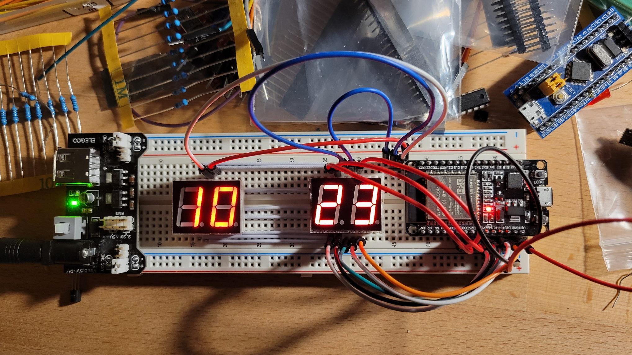
7 Segment display built with an ESP32 and programmed with the Arduino HAL through PlatformIO
Introduction
Recently I visited my hometown of Vancouver, BC. While there, I decided to take a trip to Lee’s Electronics Store where among many other things, I picked up some two digit 7 segment displays. I thought getting them up and running would be a simple and fun project to get some experience working with micro-controllers and breadboards.
7 Segment Displays
7 Segment displays are very interesting little devices. Even more interesting than the devices is how we drive them. First off, 7 Segment displays primarily come with two types of internal wiring: Common Cathode and common Anode. When driving the displays with a micro controller such as an ESP32 as I did, the only difference it makes is how you write the program.
Driving the Displays
Driving 7 Segment displays is all about voltage control. In order to fully understand how to drive these displays, we must first know that LED’s emit light based on a difference in voltage between their anode and cathode. Specifically, the anode must have a higher voltage than the cathode. Normally, we would turn an led on and off by applying a voltage to the anode and current would flow through the led and into ground. Then, when we want to turn the led off, we can simply remove the voltage. However, since light is generated through a voltage drop across the LED, we can also turn the LED off through the addition of voltage onto the cathode, thus removing the voltage potential and turning the LED off. This is the basic principle of how we can drive a seven segment display. Though maybe not useful when only driving a single digit, this method allows us to drive additional digits with only one extra wire.
The Code
In this project I used common anode displays. This means that when controlling the displays, I had to set the digit pin I wanted to use to HIGH and and set the segment I wanted lit up to LOW. That way a positive voltage potential is created between the LEDs anode (digit pin) and its cathode (segment pin). Controlling additional digits simply requires switching the pins fast enough so that the correct segment and digit pins are set to the right values at the right time. Something you may notice with my code example given below is that the numbers array was actually set up for common cathode displays while the rest of the program is set up for common anode displays. Therefore for my project I actually inverted the array using the C++ ! operator.
The Counter Program
The counter program is the simple program you see below. It includes some example code for controlling the 7 segment display as well as displaying an incrementing number on it. This code is is very similar to something like a clock, and could be easily modified for such a purpose.
Making a counter program in itself is a very simple task. However, when trying to display it on a 7 segment display, there are some factors we must take into consideration. The most of important of which is overflow.
Within my example problem, I controlled overflow by creating separate variables. The first of which is timer, this variable stores the number of milliseconds that have passed in order to determine when to update the number on the display. Four other variables; a, b, c, and d are used to store the number that is displayed on the digits. In my example, I had four digits, therefore, I also had four variables. The program from this point on is quite simple. Add one to the last digit, if that number is over 9 (the maximum value a single digit can have) then set that digit to zero and add one to the digit on the left. Following this procedure the display is able to count 0009, 0010, 0011, …, 2184 and so on.
Example Code
1
2
3
4
5
6
7
8
9
10
11
12
13
14
15
16
17
18
19
20
21
22
23
24
25
26
27
28
29
30
31
32
33
34
35
36
37
38
39
40
41
42
43
44
45
46
47
48
49
50
51
52
53
54
55
56
57
58
59
60
61
62
63
64
65
66
67
68
69
70
71
72
73
74
75
76
77
78
79
80
81
82
83
84
85
86
87
88
89
90
91
92
93
94
95
96
97
98
99
100
101
102
103
104
105
106
107
108
109
110
111
112
113
114
115
116
117
118
119
120
121
122
123
124
125
126
127
128
129
130
131
132
133
134
135
136
137
138
/**
 * @file main.cpp
 * @author Jacob Chisholm (jchisholm204.github.io)
 * @brief 4 Number 7 Segment Display Counting Example
 * @version 1.0
 * @date 2023-01-06
 *
 * @copyright Copyright (c) 2023
 *
 * Increment a counter by 1 every 1000_ms.
 * Simple program that shows how to use a 4 number 7 segment display.
 *
 * Made for ESP32-WROOM-32
 */

#include <Arduino.h>

// set up pins
//                    a   b   c   d   e   f   g   dt
uint8_t segments[] = {33, 25, 26, 12, 14, 32, 13, 27};
//                    0   1  2   3
uint8_t num_pins[] = {18, 5, 19, 21};


// FOR COMMON CATHODE
// ! FOR COMMON ANODE
bool numbers[10][8] = {
// a  b  c  d  e  f  g  dt
  {1, 1, 1, 1, 1, 1, 0, 0}, // 0
  {0, 1, 1, 0, 0, 0, 0, 0}, // 1
  {1, 1, 0, 1, 1, 0, 1, 0}, // 2
  {1, 1, 1, 1, 0, 0, 1, 0}, // 3
  {0, 1, 1, 0, 0, 1, 1, 0}, // 4
  {1, 0, 1, 1, 0, 1, 1, 0}, // 5
  {1, 0, 1, 1, 1, 1, 1, 0}, // 6
  {1, 1, 1, 0, 0, 0, 0, 0}, // 7
  {1, 1, 1, 1, 1, 1, 1, 0}, // 8
  {1, 1, 1, 0, 0, 1, 1, 0}  // 9
};

void setup() {
  for (int i = 0; i < 8; i++)
  {
    pinMode(segments[i], OUTPUT);
  }
  for (int i = 0; i < 4; i++)
  {
    pinMode(num_pins[i], OUTPUT);
  }
}

// FOR COMMON ANODE
void set(uint8_t segment, uint8_t number){
  switch (segment)
  {
  case 0:
    digitalWrite(num_pins[0], HIGH);
    digitalWrite(num_pins[1], LOW);
    digitalWrite(num_pins[2], LOW);
    digitalWrite(num_pins[3], LOW);
    for (int i = 0; i < 8; i++)
    {
      digitalWrite(segments[i], !numbers[number][i]);
      //Serial.printf("%d %d %d\n", i, segments[i], numbers[0][i]);
    }
    break;
    case 1:
    digitalWrite(num_pins[0], LOW);
    digitalWrite(num_pins[1], HIGH);
    digitalWrite(num_pins[2], LOW);
    digitalWrite(num_pins[3], LOW);
    for (int i = 0; i < 8; i++)
    {
      digitalWrite(segments[i], !numbers[number][i]);
    }
    break;
    case 2:
    digitalWrite(num_pins[0], LOW);
    digitalWrite(num_pins[1], LOW);
    digitalWrite(num_pins[2], HIGH);
    digitalWrite(num_pins[3], LOW);
    for (int i = 0; i < 8; i++)
    {
      digitalWrite(segments[i], !numbers[number][i]);
    }
    break;
    case 3:
    digitalWrite(num_pins[0], LOW);
    digitalWrite(num_pins[1], LOW);
    digitalWrite(num_pins[2], LOW);
    digitalWrite(num_pins[3], HIGH);
    for (int i = 0; i < 8; i++)
    {
      digitalWrite(segments[i], !numbers[number][i]);
    }
    break;

  default:
    break;
  }
}

// overflow counters (for individual segments)
int a = 0;
int b = 0;
int c = 0;
int d = 0;
// loop timer
int timer = 0;

void loop() {
  set(0, a);
  delay(2); // 2_ms delay for switching between numbers
  set(1, b);
  delay(2); // 2_ms delay for switching between numbers
  set(2, c);
  delay(2); // 2_ms delay for switching between numbers
  set(3, d);
  delay(2); // 2_ms delay for switching between numbers
  timer +=8; // increment timer (2_ms * 4)

  if(timer > 1000){ // update counters every 1000_ms
    d++;
    if(d>9){
      c++;
      d=0;
    }
    if(c>9){
      b++;
      c=0;
    }
    if(b>9){
      a++;
      b=0;
    }
    timer = 0;
  }
}
Conclusion
All in all this was a very fun little project and I enjoyed sharing what I learned. Since seeing this style of control I have come up with many new ideas for future projects. Some of which expansions are simple expansions of what was done here. Either way this was a good project to get a little bit of experience working with ESP32, 7 segment displays, and breadboards.