Miniature Autonomous Vehicle
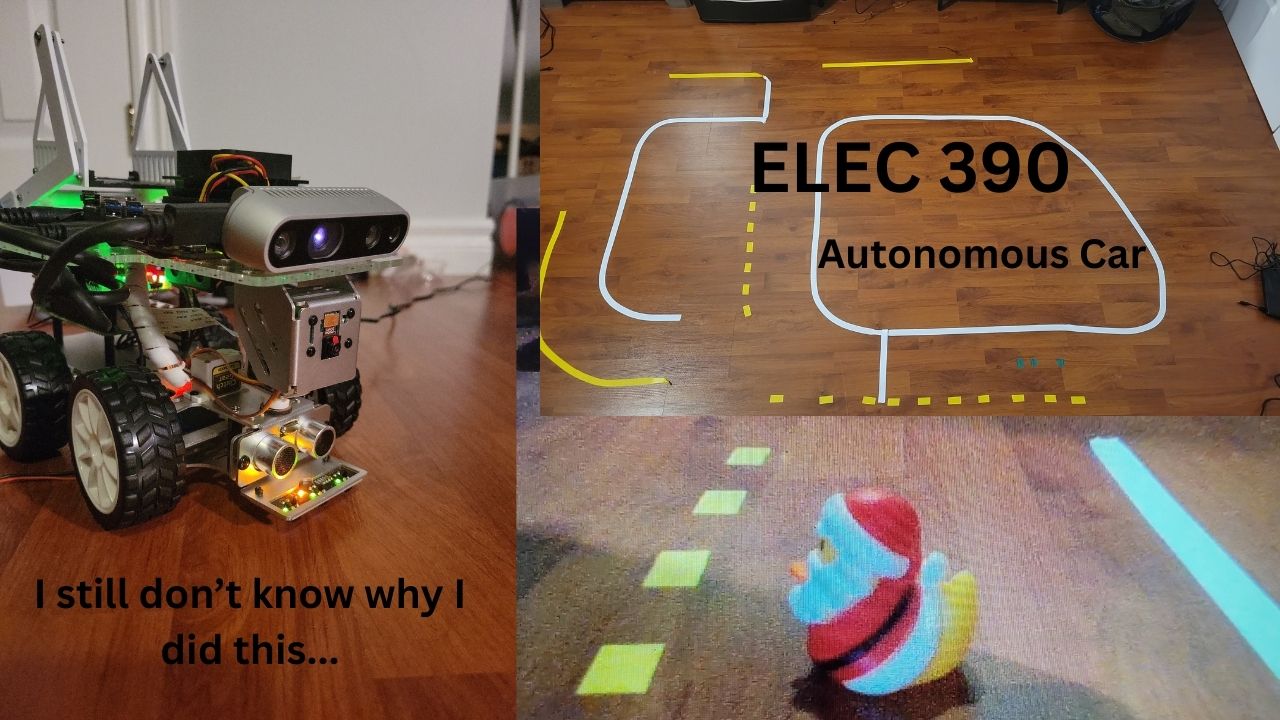
The objective of this project was to develop a miniature autonomous vehicle. Requirements for the vehicle included lane following, navigating intersections, and avoiding pedestrians.
System Requirements
This project was completed as part of one of my university courses. The objective of the course was to develop a miniature autonomous vehicle capable of navigating a town filled with rubber ducks. (See Below)
Basic project requirements included:
- Vision recognition of ducks on the road
- Vision recognition of stop signs
- Handling intersections
- Right and left turns
- Autonomous navigation
- Autonomous driving
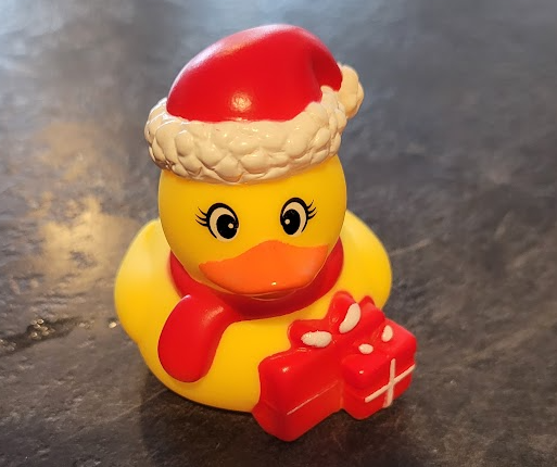 The Citizen In Question
Project Resources
This section details the resources needed to complete the project. Several provided resources were given and used. However, due to the open nature of the project, several additional resources were also used.
Provided Resources
The following list of resources was given to complete the project:
- PiCarX
- Raspberry Pi 4
- Coral Edge TPU
- Raspberry Pi Camera
The PiCarX was provided as a mechanical base. It supports individual control of its two rear motors and three servos. One of the servos is used for steering while the other two are used for controlling camera orientation.
Warning Several issues were encountered when attempting to use the code provided by SunFounder, the manufacturer. These issues will be covered in detail in a later section. If using this hardware, see this fix.
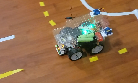 Picture of the vehicle (With some modifications)
Non-Provided Resources
In addition to the provided resources, this project also used:
- Nvidia Jetson Nano
- Intel RealSense D435
- PWM Motor Driver
NOTE These resources are only necessary to implement “passenger” (duck) avoidance. The rest of this project can be implemented in the base PiCarX hardware.
Several free software resources were also used:
- ROS 2 Humble (Robot Operating System)
- Intel RealSense ROS Node
- Camera-ROS
- Ubuntu (22LTS)
- TMUX (Terminal Multiplexer)
- OpenCV
System Design
The system design was heavily influenced by the above objectives. To achieve autonomous driving, the car must be able to detect and follow road lines, adhere to road regulations, and avoid the “pedestrians”. Furthermore, it must also be able to autonomously navigate.
Road Line Following
The outer road line consists of a white line on a black background. Using a combination of Canny’s Transform and Huges Algorithm, this line can be easily recognised. A simple controller can then be used to adjust the steering angle based off of the line displacement from its origin. To aid in the modularity of the software, the steering control can be separated from the vision algorithm.
Adhering to Road Regulations
Adhering to road regulations includes following the basic rules of the road such as stopping at intersections and cross walks. Intuitively, this could be accomplished through vision recognition of road signs. However, the PiCarX features a grey-scale sensor on the front bumper. Therefore, given that all intersections and cross walks are preceded by a stop line, this sensor can be used to trigger the appropriate action. As a result, the computation required is far less than that required by a machine learning algorithm such as YOLO (You Only Look Once). Consequently, the time to stop is much smaller than when using a vision model.
Avoiding Pedestrians
In rare cases, a pedestrian may be on the road. Special care must be taken to not collide with the pedestrian. Thus, the vehicle must have a method to recognise pedestrians and stop when they are in the way of the vehicle. Again, this could be intuitively solved with a machine learning model. However, with access to an Intel RealSense camera, the depth and infrared streams can be utilised to easily detect ducks, and other obstacles, on the road.
Take the following images as an example. The first image shows three ducks on the road. The second image shows the same ducks, but captured from the infrared stream. Note the brightness of the two ducks closest to the camera.
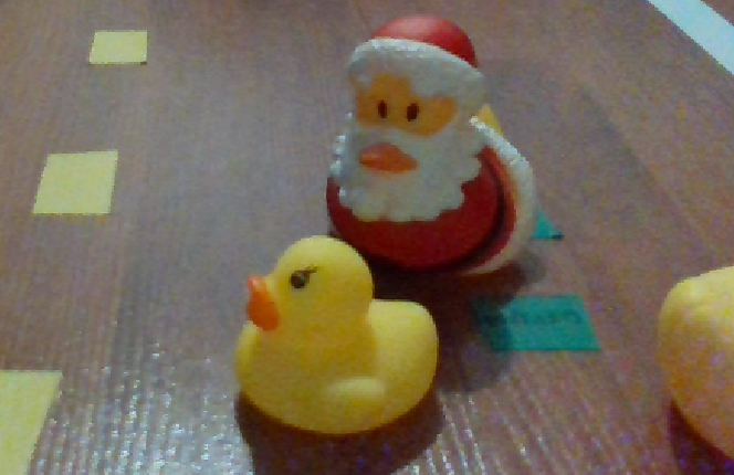 Image of Ducks on the road
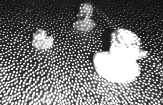 IR Image of Ducks on the road
Utilising this information, a blur filter and threshold can be applied to achieve the following outcome:
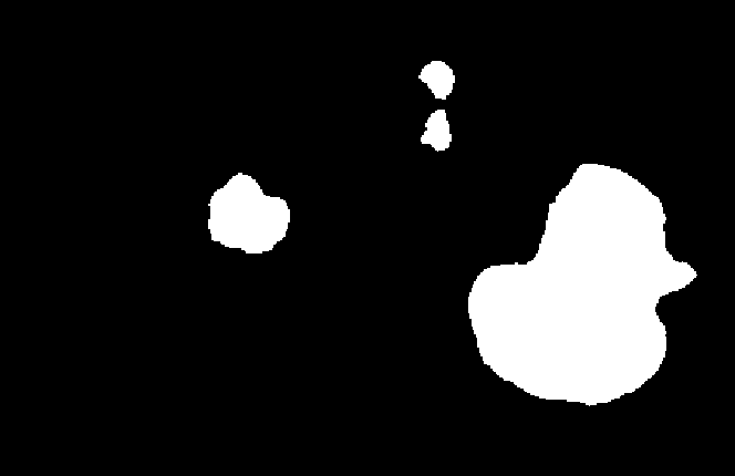
Finally, the size and position of the duck can be evaluated to determine if the vehicle needs to stop.
Autonomous Navigation
Autonomous navigation encompasses the driving control and path execution. The driver control node is able to navigate from intersection to intersection, pausing at each intersection for the next instruction.
As a result, the vehicle only achieves basic self driving functionality. However this level was more than functional for the purposes of this course and project.
System Implementation
Each of the above components communicates through the Robot Operating System (ROS). This system was chosen for its several gaping security vulnerabilities, which allowed for easy debugging of the system. However, using ROS requires first creating a node to interface with the Sunfounder PiCarX.
Fortunately, Sunfounder provides Python interfaces for their PiCarX Hat. Unfortunately, in testing this code, several fatal flaws were discovered. To list a few, the motors were not individually controllable, the car struggled to turn one way, and the camera twitched. After some light debugging, it was found that the primary cause of these issues was due to incorrect PWM constants. However, given that this code would largely have to be rewritten to interact with ROS, it only made sense to start from scratch using C++. The full ROS node is available on GitHub - Pix_Driver Node, key components are mentioned below.
On initialisation, the code connects to the Pi Hat over I2C. Unless additional I2C devices are added, the Pi Hat will be under /dev/i2c-1. The I2C connection controls the PWM outputs, and ADC’s for the grey-scale sensor. Using a logic analyser, the PWM constants were able to be set up properly and accommodate a variety of servos. Additionally, it also initialises the GPIO pins that are used for ultrasonic distance readings and motor direction controls.
Drive motors are individually controllable. The ROS node takes advantage of this through applying a differential speed to the motors based on the turn angle. The steeper the turn angle, the slower the inside wheel moves. With this parameter tuned, the vehicle maintains tighter turns and more consistent steering.
The Driver
The Driver node is responsible for the control of the vehicle. It interfaces with the pix (PiCarX) code, handling the drive speed and steering control. Additionally, it handles line following, passing through intersections, and stopping for ducks on the road. It achieves this behaviour through a state machine with the following states:
1
2
3
4
5
6
7
8
9
10
11
12
13
14
15
16
enum eState {
	eState_Driving,
	eState_Blocked,
	eState_Waiting,
	eState_Turn_Right,
	eState_Turn_Left,
	eState_Turn_Straight
};
std::unordered_map<enum eState, std::string> stateString = {
	{eState_Driving, "Driving"},
	{eState_Blocked, "Blocked"},
	{eState_Waiting, "Waiting"},
	{eState_Turn_Right, "Turn Right"},
	{eState_Turn_Left, "Turn Left"},
	{eState_Turn_Straight, "Going Straight"},
};
Driving State
When in the driving state, the drive speed is a fixed positive value. The turn angle is controlled based on data from the road line detection node. The optimum position of the line on the screen was recorded. A PID along with motion smoothing was applied generate the turn angle value.
1
2
3
4
5
6
7
8
9
10
11
12
13
14
15
void Driver::line_dev_callback(const std_msgs::msg::Float32::SharedPtr msg){
    error = -(msg->data - 42);
    float derr = (error - error_last);
    error_sum = (error + error_sum)/2;
    error_last = error;
    float p = this->param_pid_p*error;
    float i = this->param_pid_i*error_sum;
    float d = this->param_pid_d*derr;
    float pow = p + i + d;
    float exp = pow;//exponential(pow, 1.2, 2, 0, 30);
    if(exp >= 30) exp = 30;
    if(exp <= -30) exp = -30;
    this->turn_angle = exp*this->param_turn_factor + this->turn_angle*(1-this->param_turn_factor);
    this->drive_pow = this->param_drive_power;
}
The driving state is the default state, and can be interrupted by any other event occurring.
Blocked State
The blocked state is entered when the detection algorithm detects an obstacle. Specifically, when one of the detected obstacles exceeds a size threshold. The blocked state can also be entered when the ultrasonic measures a distance below its minimum threshold.
Upon entering the blocked state, the current state is backed up. The block state can only be exited when the condition that caused the block state is no longer present. When the blocked state is exited, the backed up state is resumed.
Waiting State
The waiting state is analogous to the driving state. However, in the waiting state, the drive power is set to zero. The waiting state is entered when the vehicle approaches an intersection. This is detected by a threshold trigger on the grey-scale sensor.
When in the waiting state, the the motors and servos are set to their zero positions. The code for the waiting state is shown below:
1
2
3
4
5
6
case eState_Waiting:
	drive_msg.data = 0;
	this->drive_pow_pub->publish(drive_msg);
	turn_msg.data = 0;
	this->turn_pub->publish(turn_msg);
	break;
Turning States
Turning is accomplished through setting the steering angle to a fixed value, and driving for a set period of time. This was implemented through a ROS callback timer. Upon entering a turning state, the last intersection time is updated. The following code make the required comparisons to determine if the timer has elapsed. Upon the timer elapsing, the system state is changed to driving.
1
2
3
4
5
6
7
8
9
10
11
12
13
14
15
16
17
18
19
20
21
void Driver::intersection_timer_callback(void){
    // Switch state back to driving after timer elapsed
    auto now = this->now();
    rclcpp::Duration elapsed_time = now - last_intersection;

    switch(this->state){
        case eState_Driving:
        case eState_Blocked:
        case eState_Waiting:
            break;
        case eState_Turn_Left:
        case eState_Turn_Right:
        case eState_Turn_Straight:
            // Convert param_intersection_time to seconds (since Duration uses seconds by default)
            if(elapsed_time.seconds() * 1000.0 >= param_intersection_time) {
                this->state = eState_Driving;
            }
            RCLCPP_INFO(this->get_logger(), "Time Remaining = %0.4f", (float)this->param_intersection_time/1000.0 - elapsed_time.seconds());
            break;
    }
}
Thus, after executing one of the turn states at an intersection, the vehicle will continue driving until the next intersection is reached.
Road Line Detection
Following road lines was accomplished using the algorithm described above and implemented using OpenCV. The ROS-CV bridge was used to openly broadcast camera feeds, allowing them to be processed with OpenCV, or viewed by an external device. This “functionality” allows for simplistic and real time debugging. The Transfer function is shown below:
1
2
3
4
5
6
7
8
9
10
11
12
13
14
void LineTracker::cv_callback(const sensor_msgs::msg::Image::SharedPtr msg){
    cv::Mat frame;
    try{
        // Convert ROS2 Image message to OpenCV Mat (YUYV format)
        cv_bridge::CvImagePtr cv_ptr = cv_bridge::toCvCopy(msg, "yuv422_yuy2"); // Load only Y channel

        // Convert YUYV to BGR using OpenCV
        cv::cvtColor(cv_ptr->image, frame, cv::COLOR_YUV2BGR_YUY2);
    }
    catch (const cv_bridge::Exception &e){
        RCLCPP_ERROR(this->get_logger(), "Failure: %s", e.what());
    }
    this->process_image(cv::Mat frame);
}
The process image function performs the algorithm required to detect the road line. Its implementation is shown below:
1
2
3
4
5
6
7
8
9
10
11
12
13
14
15
16
17
18
19
20
21
22
23
24
25
26
27
28
29
30
31
32
33
34
35
36
37
38
39
40
41
42
43
44
45
46
47
48
49
50
51
52
cv::Mat gray;
cv::cvtColor(frame, gray, cv::COLOR_BGR2GRAY);
cv::medianBlur(gray, gray, 13);
// Threshold the image
cv::Mat thresholded;
cv::threshold(gray, thresholded, 110, 255, cv::THRESH_BINARY);

cv::Mat cv_out;
cv::cvtColor(thresholded, cv_out, cv::COLOR_GRAY2BGR);

// Compute image moments
cv::Moments moments = cv::moments(thresholded, true);
cv::Point center;
// Check if the moment is valid (avoid division by zero)
if (moments.m00 > 0) {
    center.x = static_cast<int>(moments.m10 / moments.m00);
    center.y = static_cast<int>(moments.m01 / moments.m00);
    // Draw a dot at the centroid
    cv::circle(cv_out, center, 5, cv::Scalar(0, 255, 255), -1);
}

// Find the white line using HoughLinesP
std::vector<cv::Vec4i> lines;
cv::Mat canny;
cv::Canny(thresholded, canny, 100, 200);
cv::HoughLinesP(canny, lines, 1, CV_PI / 180, 50, 50, 10);

if (!lines.empty()) {
    float average_reading = 0;
    cv::Point avg;
    for(size_t i = 0; i < lines.size(); i++){
        cv::Vec4i l = lines[i];
        int x_center = (l[0] + l[2]) / 2;
        int y_center = (l[1] + l[3]) / 2;
        // Blend Hough & Moments
        cv::Point final_center = cv::Point((center.x + x_center) / 2, (center.y + y_center) / 2);
        avg.x += final_center.x;
        avg.y += final_center.y;

        average_reading += final_center.y - static_cast<float>(msg->height) / 2.0;
        average_reading -= final_center.x - static_cast<float>(msg->width) / 2.0;
    }
    average_reading /= (float)lines.size();
    avg.x /= lines.size();
    avg.y /= lines.size();
    cv::circle(cv_out, avg, 5, cv::Scalar(0, 0, 255), -1);
    // Publish the deviation from the center of the image
    std_msgs::msg::Float32 line_dev_msg;
    // line_dev_msg.data = (average_reading + center.y - center.x)/2.0;
    line_dev_msg.data = average_reading;
    this->line_dev_pub->publish(line_dev_msg);
}
This achieves the following result:
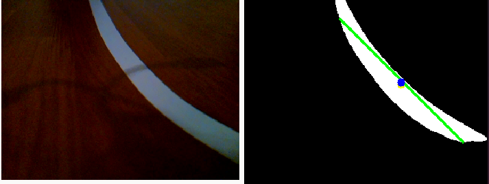 Road Line Detection
Obstacle Avoidance
Obstacle avoidance was implemented using a copy of the road line detection algorithm. However, rather than using a color image, it uses an infrared image. This allows it to easily spot ducks on the road as shown below:
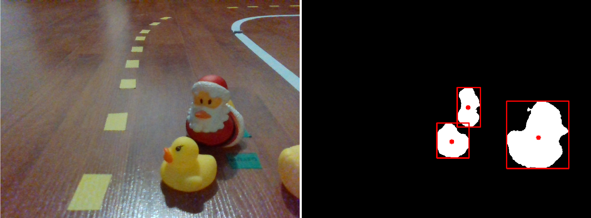 Duck Detection
The full implementation is shown below:
1
2
3
4
5
6
7
8
9
10
11
12
13
14
15
16
17
18
19
20
21
22
23
24
25
26
27
28
29
30
31
32
33
34
35
36
37
38
39
40
41
42
43
44
45
46
47
48
49
50
51
52
53
54
55
56
57
58
59
60
61
if(infra.empty()) return;
cv::Mat thresholded_infra;
cv::medianBlur(infra, thresholded_infra, 17);

// Create a gradient mask that darkens towards the bottom (same size as input, single channel)
// This helps remove the floor
cv::Mat gradient_mask(thresholded_infra.size(), CV_32FC1);
for (int y = 0; y < gradient_mask.rows; y++) {
	float alpha = 1.0f - (0.70f * y / gradient_mask.rows); // 0.8 means we keep 20% brightness at bottom
	gradient_mask.row(y).setTo(cv::Scalar(alpha));
}

// Convert binary image to float (single channel)
cv::Mat float_infra;
thresholded_infra.convertTo(float_infra, CV_32FC1, 1.0/255.0);

// Apply gradient
cv::Mat result;
cv::multiply(float_infra, gradient_mask, result);

// Convert back to 8-bit
result.convertTo(thresholded_infra, CV_8UC1, 255.0);

// threshold image
cv::threshold(thresholded_infra, thresholded_infra, 110, 255, cv::THRESH_BINARY);

// Find Contours in the Image (Obstacles)
// Find contours
std::vector<std::vector<cv::Point>> contours;
std::vector<cv::Vec4i> hierarchy;
cv::findContours(thresholded_infra, contours, hierarchy, cv::RETR_EXTERNAL, cv::CHAIN_APPROX_SIMPLE);

// Draw bounding boxes around each contour
cv::Mat result_image;
cv::cvtColor(thresholded_infra, result_image, cv::COLOR_GRAY2BGR);

// Obstacles Vector
std::vector<geometry_msgs::msg::Point32> obstacles;

for (size_t i = 0; i < contours.size(); i++) {
	// Get the bounding rectangle for each contour
	cv::Rect bounding_box = cv::boundingRect(contours[i]);

	// Draw a rectangle around the obstacle
	cv::rectangle(result_image, bounding_box, cv::Scalar(0, 0, 255), 2);
	cv::Moments moments = cv::moments(contours[i]);
	int center_x = static_cast<int>(moments.m10 / moments.m00);
	int center_y = static_cast<int>(moments.m01 / moments.m00);

	// Draw a dot at the center of the obstacle
	cv::circle(result_image, cv::Point(center_x, center_y), 5, cv::Scalar(0, 0, 255), -1);

	// Push back to obstacle array
	geometry_msgs::msg::Point32 point;
	point.x = center_x;
	point.y = center_y;
	// Use Z to store area of obstacle
	point.z = bounding_box.width*bounding_box.height;
	obstacles.push_back(point);
}
The code publishes this result as a point cloud. Each point in the point cloud contains the $(x, y)$ position of the object, and its size. The size is stored in the point clouds $z$ dimension. It also publishes the processed images for debugging.
1
2
3
4
5
6
7
8
9
10
11
12
13
14
15
16
17
// Create the PointCloud message
sensor_msgs::msg::PointCloud point_cloud_msg;
point_cloud_msg.header.stamp = this->now();
point_cloud_msg.header.frame_id = "none";
point_cloud_msg.points = obstacles;

// Publish the PointCloud message
this->obstacles_pub->publish(point_cloud_msg);

// Publish the result image for debugging
cv_bridge::CvImage out_image = cv_bridge::CvImage();
std_msgs::msg::Header header;
header.stamp = this->now();
out_image.header = header;
out_image.encoding = sensor_msgs::image_encodings::BGR8;
out_image.image = result_image;
this->image_pub->publish(*out_image.toImageMsg());
Results
See the following video for the end results.