Embedded CRSF Driver
Crossfire (CRSF) is a high level communication protocol developed by Team Black Sheep (TBS) for transmitting control and telemetry data between a receiver and Flight Controller (FC). Originally intended for use in TBS devices, the protocol is now implemented in nearly every FC firmware and is used by most off-the-shelf receivers including ExpressLRS and Tracer.
This article serves as an introduction to the CRSF protocol (Skip Ahead) and as documentation for my FreeRTOS Queue based implementation of a CRSF packet encoder/decoder (Skip Ahead).
CRSF Protocol Basics
Crossfire (CRSF) is a high-speed, low latency communication protocol for sending and receiving control and telemetry data between a drone and controller.
The following section will focus on the CRSF packet structure, device addressing, base message types, and how to format a CRSF message for transmission.
CRSF Packet Structure
The basic structure of every CRSF packet is identical, consisting of an address, length, type, payload, and CRC.
1
<address> <length> <type> <payload ... > <CRC>
The address, length, type, and CRC are each one byte (8 bits). The payload can range from $2$ to $62$ bytes to accommodate various message formats. Note that the length field excludes the address. Therefore, length is calculated as:
\[Len(payload) + Len(type) + Len(CRC) = Len(payload)+2\]Additionally, the CRC is calculated on only the type and payload, excluding the address and length bytes.
Device Addressing
Each CRSF message contains an “address” field, denoting the address of the transmitting/receiving device. The primary address used is 0xC8, corresponding to the flight controller. This address must be used when sending/receiving messages to/from the flight controller. Other possible addresses are shown in the table below:
| Address | Device Description |
|---|---|
| 0x00 | Broadcast address |
| 0x10 | USB Device |
| 0x12 | Bluetooth Module |
| 0x80 | TBS CORE PNP PRO |
| 0x8A | Reserved |
| 0xC0 | PNP PRO digital current sensor |
| 0xC2 | PNP PRO GPS |
| 0xC4 | TBS Blackbox |
| 0xC8 | Flight controller |
| 0xCA | Reserved |
| 0xCC | Race tag |
| 0xEA | Radio Transmitter |
| 0xEB | Reserved |
| 0xEC | Crossfire / UHF receiver |
| 0xEE | Crossfire transmitter |
Message Types
The CRSF protocol contains message types for both control and telemetry data. The following section outlines the base message types used by INAV and Betaflight. Custom message types can be used, but require implementation on the FC side.
NOTE The number next to the each message is its ID in hex.
RC Message (0x16)
The Remote Control (RC) message can be used to transmit stick commands from a device or receiver to the flight controller. The RC message supports up to 16 RC channels. Each channel is 11 bits and the 16 channels are packed into a 22 byte format. The message format is shown below:
1
2
3
4
5
6
7
struct rc_channels_msg{
	unsigned int chnl1 : 11;
	unsigned int chnl2 : 11;
	unsigned int chnl3 : 11;
	...
	unsigned int chnl16 : 11;
};
Many receivers and FC firmware’s represent channels using $\mu$s. CRSF however, uses ticks. Therefore the following functions must be used to convert between the two measurements.
1
2
TICKS_TO_US(x) ((x - 992) * 5 / 8 + 1500)
US_TO_TICKS(x) ((x - 1500) * 8 / 5 + 992)
Link Statistics Message (0x14)
The link statistics message contains status information for the link between the receiver and the transmitter. Uplink is the connection between the ground and UAV, downlink is the connection from the UAV to the ground station.
1
2
3
4
5
6
7
8
9
10
11
12
13
14
15
16
17
18
19
20
21
22
struct __attribute__((packed)) {
    // dBm *-1
    uint8_t uplink_RSSI_1;
    // dBm *-1
    uint8_t uplink_RSSI_2;
    // percent
    uint8_t uplink_quality;
    // uplink SNR (db)
    int8_t uplink_SNR;
    // enum ant 1 = 0, 2
    uint8_t diversity_active_antenna;
    // enum Mode (4fps = 0, 50fps, 150Hz)
    uint8_t RF_mode;
    // enum (0mW, 10mW, 25mW, 100mW, 500mW, 1000mW, 2000mW)
    uint8_t tx_power;
    // dBm * -1
    uint8_t downlink_RSSI;
    // percent
    uint8_t downlink_quality;
    // db
    int8_t downlink_SNR;
} _crsf_link_t;
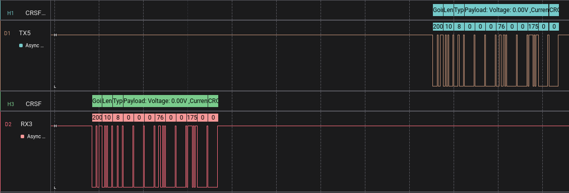
Battery Status Message (0x08)
The battery status message contains exactly the information one would expect. Its format is as follows:
1
2
3
4
5
6
7
8
9
10
typedef struct __attribute__((packed)) {
    // mV * 100
    uint16_t voltage;
    // mA * 100
    uint16_t current;
    // mAh (24 bits)
    unsigned int capacity : 24;
    // percent (0-100]
    uint8_t percent_remaining;
} _crsf_battery_t;
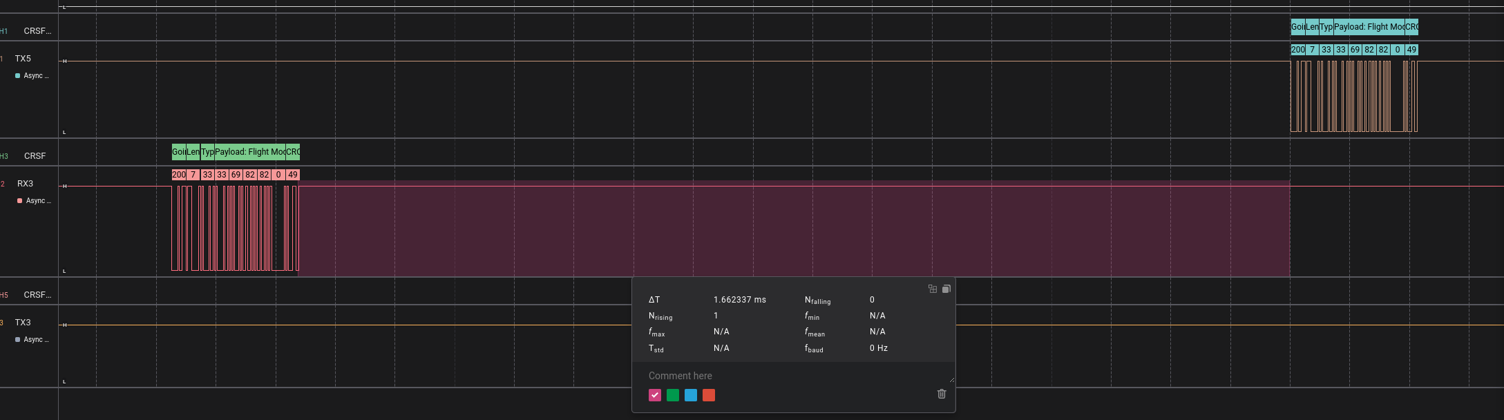
Flight Mode Message (0x21)
The flight mode message contains a null terminated string indicating the current flight mode of the FC. This field is FC firmware dependent. For Betaflight, the possible strings are covered under the Betaflight CRSF Documentation.
The message format is as follows:
1
2
3
struct crsf_fcmode {
    char mode[];
};
Attitude Message (0x1E)
The attitude message contains the current pitch, yaw, and roll values from the flight controllers IMU. All angles are represented in integer format, in $\frac{\text{radians}}{10,000}$.
1
2
3
4
5
struct crsf_attitude_t{
    int16_t pitch;
    int16_t roll;
    int16_t yaw;
};
GPS Message (0x02)
Finally, the GPS message contains the current GPS information, if the drone has one. The GPS message format is as follows:
1
2
3
4
5
6
7
8
9
10
11
12
13
struct crsf_gps {
    // degrees / 10_000_000
    int32_t lattitude;
    // degrees / 10_000_000
    int32_t longitude;
    // km/h / 100
    uint16_t groundspeed;
    // degree / 100
    uint16_t heading;
    // meter - 1000m offset
    uint16_t altitude;
    uint8_t sat_count;
};
Message Formatting
All of the C structures shown above conform to standard CRSF message types. Thus, they can be directly used as payloads within the CRSF message format.
To format a CRSF message for transmission, first append the address (0xC8 for the Flight Controller) and the length bits to the front of the message. Again, note that the message length excludes the address byte. Finally, calculate the 8-bit CRC using the $x^7+x^6+x^4+x^2+x^0$ hash and append it as the last byte in the message.
FreeRTOS Interface Implementation
The following section serves as documentation for my FreeRTOS Queue-based implementation of a CRSF interface. This interface is designed to completely abstract the CRSF interface, providing only read and write functions that return unpacked messages in standardized formats. Furthermore, this implementation is designed to completely abstract the CRSF layer from any hardware constraints, relying only on FreeRTOS stream buffers.
The implementation is designed around the following features:
- Only using static memory defined within the
CRSF_tstructure - Only reliant on FreeRTOS interfaces
- Independent from any hardware interfaces
- Minimal message buffering for low-latency and high throughput
Initialization
The CRSF protocol itself does not require any initialization. However, the implementation sets up an internal FreeRTOS task, used to parse the CRSF packets as bytes are delivered through the input stream buffer.
To initialize the CRSF_t structure, setup the queues, and create the internal task, the following function can be called:
1
2
3
4
5
6
7
8
9
10
11
12
13
14
15
16
17
18
19
20
21
22
23
24
25
26
27
28
29
30
StreamBufferHandle_t crsf_init(CRSF_t *pHndl, StreamBufferHandle_t pTx_hndl) {
    if (!pHndl)
        return NULL;
    if (!pTx_hndl)
        return NULL;

    // Setup Write handle
    pHndl->tx.semphr_hndl =
        xSemaphoreCreateMutexStatic(&pHndl->tx.static_semphr);
    pHndl->tx.pBuf_hndl = pTx_hndl;

    // Setup Read Handle
    pHndl->rx.hndl = xStreamBufferCreateStatic(
        configMINIMAL_STACK_SIZE, 1, pHndl->rx.buf, &pHndl->rx.static_stream);

    // Setup the CRSF rx task
    pHndl->tsk.hndl = xTaskCreateStatic(vCRSF_Hndl_tsk,
                                        "CRSF",
                                        CRSF_STACK_SIZE,
                                        (void *) pHndl,
                                        2,
                                        pHndl->tsk.stack,
                                        &pHndl->tsk.static_tsk);
    if (!pHndl->tsk.hndl) {
        pHndl->state = eCRSFTskCreateFail;
        return NULL;
    }

    return pHndl->rx.hndl;
}
This function requires two arguments. First is the CRSF_t handle, which should be created statically at initialization time by whatever task “owns” the CRSF interface. This handle contains all information required by the interface, including the FreeRTOS task and stack as well as internal data structures and semaphores.
The second argument required by the initialization function is a FreeRTOS stream buffer handle. This handle is used to transmit messages, and must be initialized externally. External initialization of this buffer allows its size and trigger values to be configured by whichever interface will be dealing with outbound packets.
Finally, the initialization function returns its incoming buffer in the form of another FreeRTOS stream buffer handle. This buffer is used by the interface to receive and parse incoming packets.
Reading CRSF Data
The CRSF interface automatically receives and and parses packets from its input buffer as the arrive. This is done using the internal task that was setup by the initialization function. Once parsed, incoming packets are stored within the CRSF_t structure such that they can be read by an outside task. Note that after parsing, packets are not buffered, thus, only the most recent packet of each type is stored. This ensures:
- Only the most recent command/information can be read by an outside task.
- Minimal memory overhead is needed to store the parsed packets.
- Outside tasks do not need to block waiting for CRSF data
The following read functions are available:
1
2
3
4
eCRSFError crsf_read_rc(CRSF_t *pHndl, crsf_rc_t *pChannels);
eCRSFError crsf_read_battery(CRSF_t *pHndl, crsf_battery_t *pBattery);
eCRSFError crsf_read_attitude(CRSF_t *pHndl, crsf_attitude_t *pAttitude);
eCRSFError crsf_read_mode(CRSF_t *pHndl, crsf_fcmode_t *pMode);
All read functions are non-blocking and thread safe. Given that these functions return from the internal data structure, they can be called multiple times to return the same data. Data is returned through the second parameter, and is transferred via copy.
Writing CRSF Packets
Writing to the CRSF interface is a blocking operation. For a task to write out a CRSF packet, it must wait to hold the transmit semaphore.
The following write functions are available:
1
2
3
4
eCRSFError crsf_write_rc(CRSF_t *pHndl, const crsf_rc_t *pChannels);
eCRSFError crsf_write_battery(CRSF_t *pHndl, const crsf_battery_t *pBattery);
eCRSFError crsf_write_attitude(CRSF_t *pHndl, const crsf_attitude_t *pAttitude);
eCRSFError crsf_write_mode(CRSF_t *pHndl, const crsf_fcmode_t *pMode);
Each write function first copies the data from the normalized format to the CRSF format, ensuring that all data is properly formatted with the correct unit conversions. The write function also ensures that minimum and maximum value constraints are not violated by clamping input data values.
After applying the data transformation, the following internal function is called to write the packet into the output buffer:
1
2
3
4
5
6
7
8
9
10
11
12
13
14
15
16
17
18
19
20
21
22
23
24
25
eCRSFError _crsf_send_packet(CRSF_t *pHndl, _crsf_msg_t *msg, enum eCRSFMsgId id, uint8_t len) {
    if (!pHndl)
        return eCRSFNULL;
    if (!msg)
        return eCRSFNULL;

    if(len >= CRSF_DATA_MAXLEN){
        return eCRSFPktOverLen;
    }

    // Addr = CRSF Addr FC
    msg->addr = CRSF_ADDR;
    msg->length = len + 2; // type + payload + crc
    msg->type = (uint8_t) id;

    // CRC includes type and payload
    uint8_t crc = _crsf_crc8(&msg->type, len + 1);
    msg->pyld[len] = crc;

    if(xSemaphoreTake(pHndl->tx.semphr_hndl, 10) != pdTRUE){
        xStreamBufferSend(pHndl->tx.pBuf_hndl, msg, msg->length + 1, 10);
    }

    return eCRSFOK;
}
This function assumes that the length argument is the length of the data packet, allowing it to be called as shown below:
1
2
3
4
struct _crsf_rc_t rc_msg = {0};
CRSF_t crsf_interface;
...
_crsf_send_packet(&crsf_interface, &rc_msg, eCRSFMsgRC, sizeof(struct _crsf_rc_t));
Note that the CRSF interface uses two types of packet formats. Packet structures prefixed with _ are used internally, and correspond to the exact formats defined within the CRSF protocol. Structures without this prefix are designed to be used externally, are not “packed,” and contain normalized values that are easier to work with. For example, the CRSF protocol defines battery voltage as a uint16 in $mV *100$. However, it is much easier to work with a standard measurement like $V$, represented as a floating point.
Example Usage
The following code defines example usage for initializing the CRSF interface to operate over a Serial (UART) port.
1
2
3
4
5
6
7
8
9
10
11
 // Create the write handle
 StreamBufferHandle_t tx_hndl = serial_create_write_buffer(pSerial, configMINIMAL_STACK_SIZE, 1, pHndl->tx_buf, &pHndl->tx_streamBuf);

StreamBufferHandle_t rx_hndl = crsf_init(&pHndl->crsf, tx_hndl);

if (!rx_hndl) {
    printf("CRSF INI Fail\n");
}

// Attach the read handle to the Serial interface
serial_attach(pHndl->pSerial, rx_hndl);
The above code first utilizes the Serial interface to create and initialize a new Serial write buffer. Note that the FreeRTOS stream buffer memory is stored within pHndl, which is the handle of a test task containing both the serial driver and the CRSF interface. While the Serial driver memory is owned by the Serial driver layer, and the receive buffer memory is owned by the CRSF layer, the transmit buffer memory must be owned by the encapsulating task. In this case, that is the test task.
Verification
In this test, the program was required to echo decoded CRSF packets onto another Serial interface.
The CRSF interface was also tested decoding RC packets and forwarding them to a desktop computer over USB for use with the Liftoff Flight Simulator as part of Project Scout. As further testing is done, this page will be updated.